Rapidia's Conflux 1 Printer is capable of printing a wide range of part geometries. The following guide outlines the constraints users should design within to get the best results. Both printing and sintering are processes for which results can be geometry-specific, and the guidelines below may not cover all cases. Some experimentation may be necessary to get the desired properties for a given part.
¶ Designing for Conflux 1
¶ Near-Net Shape Mentality
The advantage of using a metal 3D printer is that a wide range of geometries can be printed with little additional effort on the part of the operator. However, metal 3D printers that use a “print and sinter” approach cannot achieve the tolerances required for close-fitting mating parts. Designers creating parts using the Rapidia System should adopt a “near-net-shape mentality”; that is, they should design parts keeping in mind the finishing operations (such as facing, boring, or tapping) that might need to be performed after the part is sintered, much in the same way cast or forged parts are designed. In particular, designers should avoid depending on printed surfaces for providing reference planes, and avoid printing small features that should instead be machined (such as threads).
¶ Part Orientation
If possible, parts should be oriented such that the largest side is placed on the print bed. This may not always be possible given other constraints (such as support locations) but will offer a stable adhesion to the bed. Because a printed part is composed of layers in the Z-direction, the Z dimension of the printed part must be an integer multiple of the layer height. Higher accuracy can be achieved in the X and Y directions, so important dimensions should be kept in the XY plane where possible.
¶ Table of Limitations
| *Limitations for default settings and beginner users to help boost first part success rate | |
| Accuracy | <1% of linear dimension post-sinter [%]X [%]Y [%]Zed *geometry dependant |
| Minimum Tolerance (0.4mm nozzle) |
Green [±250µm] 0.25mm layer height Post-sinter [±220µm] 0.22mm layer height |
| Dimensions [LxWxH] (mm) |
Print Bed: [243x202x150] Furnace w/two shelves: [298.5x237x123.5] + [298.5x150x53] Furnace w/one shelf: [298.5x150x181.5] Recommended part within: [100x100x100] |
| Aspect Ratio | Sintered Vertically [3:1] Sintered Horizontally [4:1] |
| Weight Limit | Wet Feedstock [~3kg] Post-sinter [~2.8kg] |
| CC usage (cm^3) | Recommended single part [<600cc] |
| Overhang Angle | Unsupported [45°] |
| Features | Emboss: [2mm] Width [1mm] Height Engrave: [1mm] Width [1mm] Depth |
| Minimum Hole Diameter | Post-sinter [2mm] |
|
Minimum Pin Diameter |
Post-sinter [Xmm] |
| Surface finish [Ra] (without green finishing) |
Wall [10µm] On Printer Bed [1µm] Interface [8µm] Top [2µm] |
| Wall thickness | Min Green [0.8mm] Post-sinter [0.7mm] Max [50mm] *carbon content may increase |
|
Maximum Bridge |
Without support: [5mm] With evaporative support: [30mm] With metal support: no limit |
| Furnace Cycle | 12/24/36 hr cycles depending on largest part being sintered *size recommendations TBA, ask our applications team |
¶ Minimizing Support
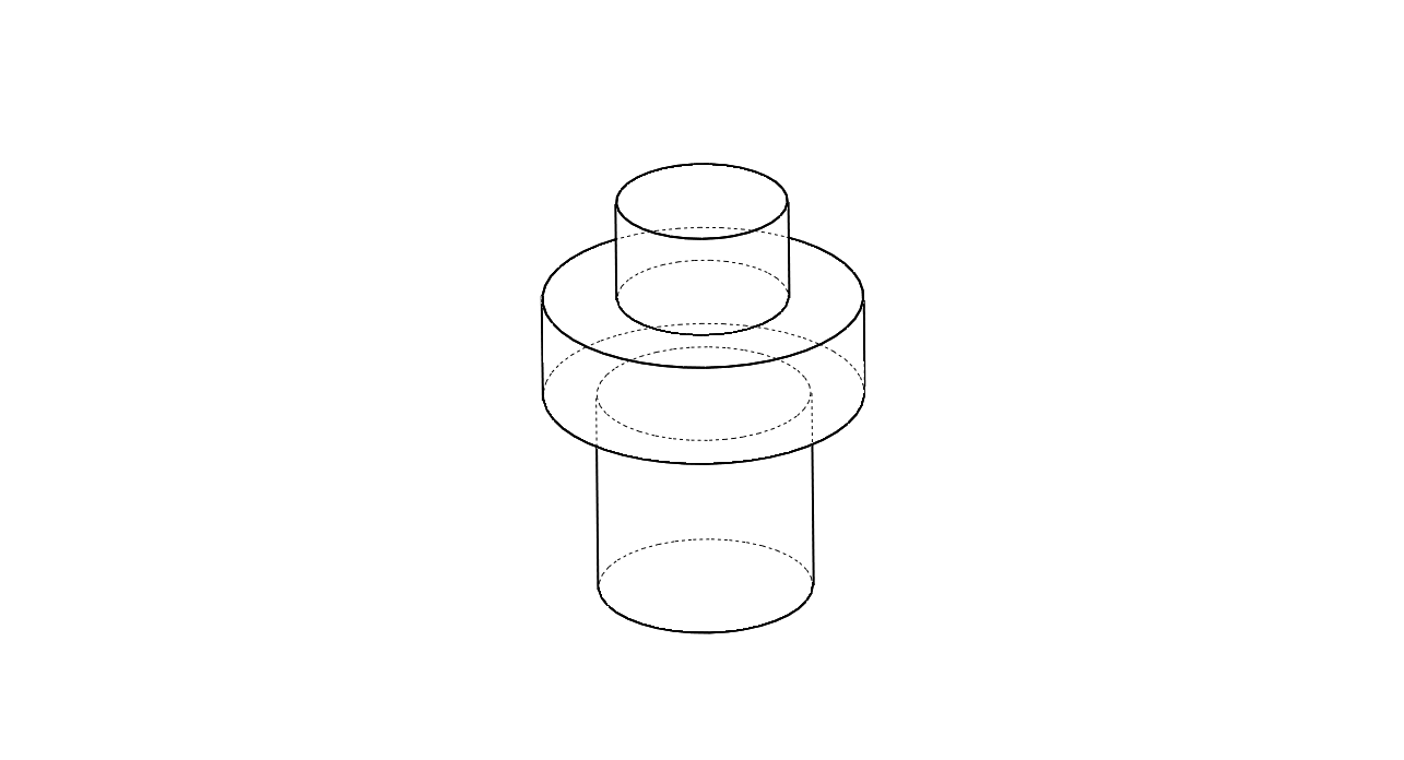
Several simple techniques can be used to reduce support material:
 |
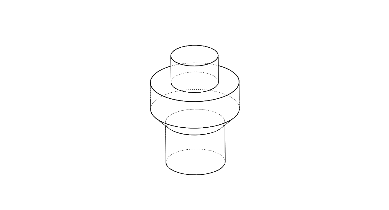 |
| 1. Eliminate sharp overhangs or orient the part to minimize overhangs. | |
 |
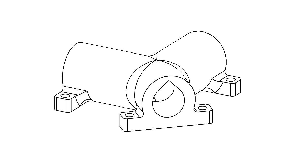 |
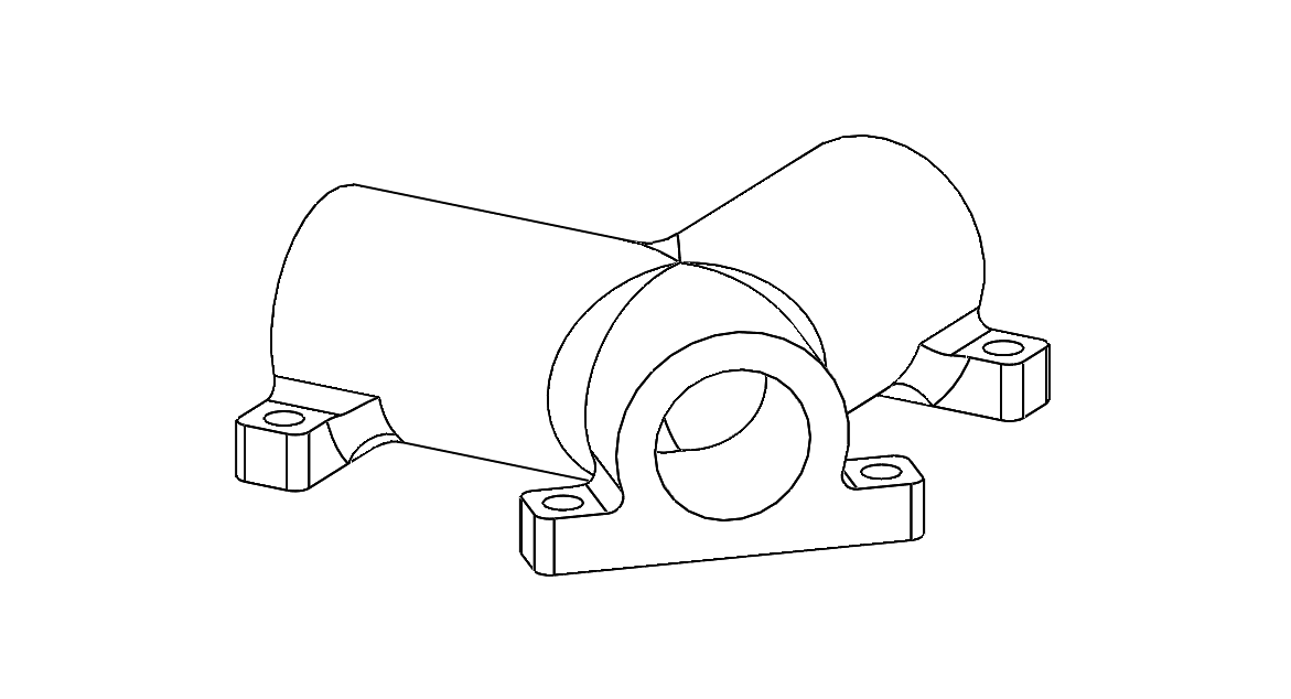
| 2. Change horizontal hole profiles to diamonds (or double-teardrops) so that they are within the overhang angle limit. Diamond-shaped holes also make good pilot holes. | |
 |
 |
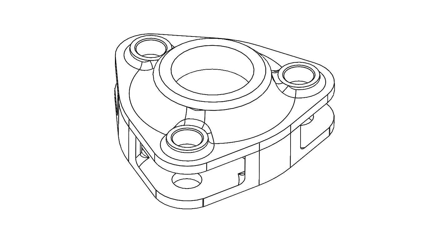 |
| 3. Consider splitting parts and assembling after sintering or Green-Bonding. | ||
¶ Adequate Support
 |
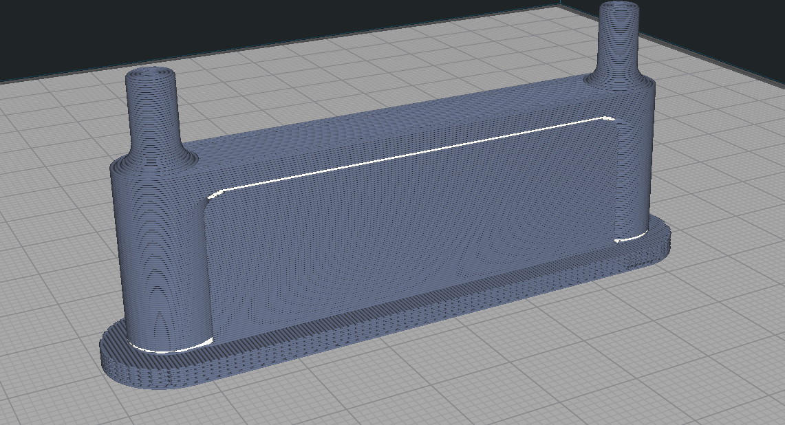 |
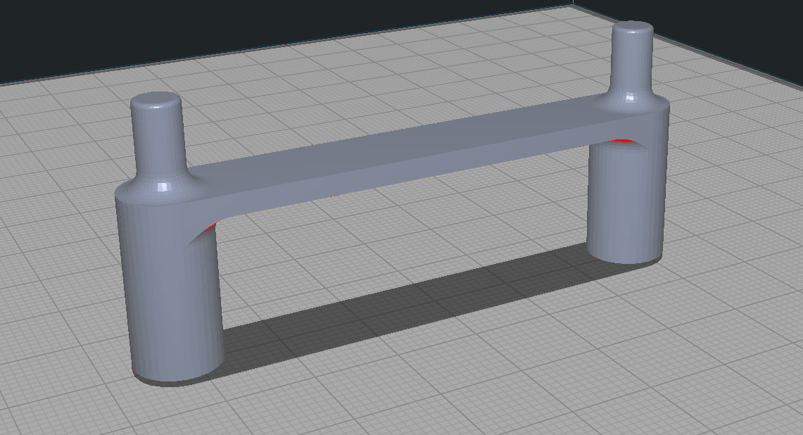
| Long spans or cantilevers should be avoided if possible, but where necessary they can be supported with metal support. | |
 |
|
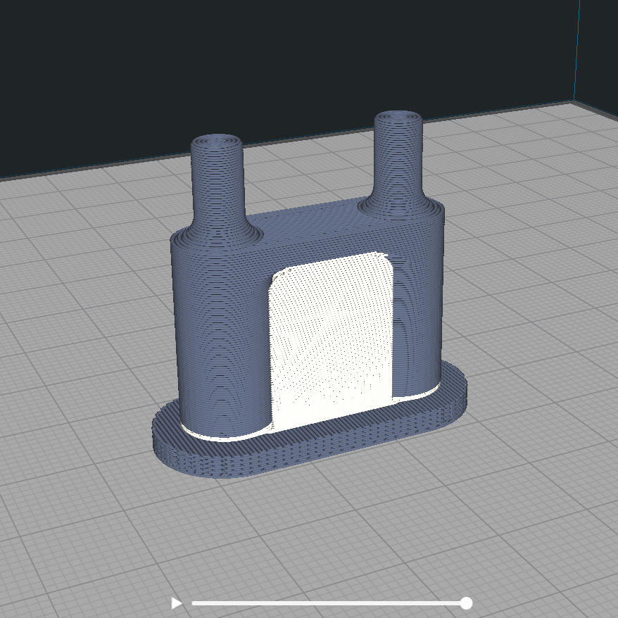
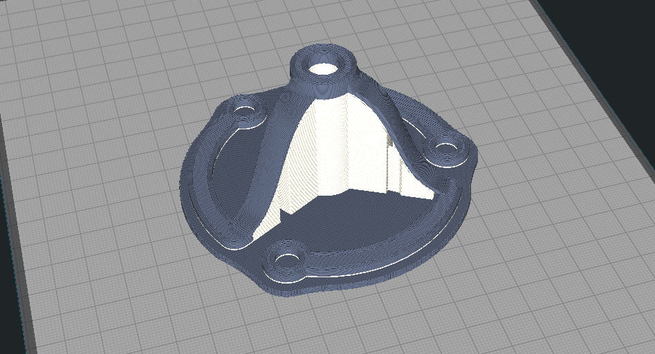
| Small overhangs and cantilevers can be supported with evaporative support. | |
 |
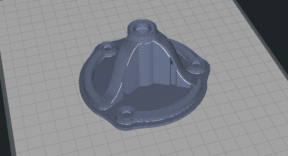 |
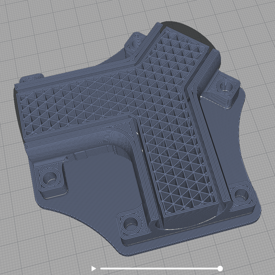
| Avoid using large pieces of evaporative support as they will cause the part to curl and may damage the part during debind. As a rule of thumb, keep the volume of the support material to a maximum of ¼ the volume of the metal. | |
 |
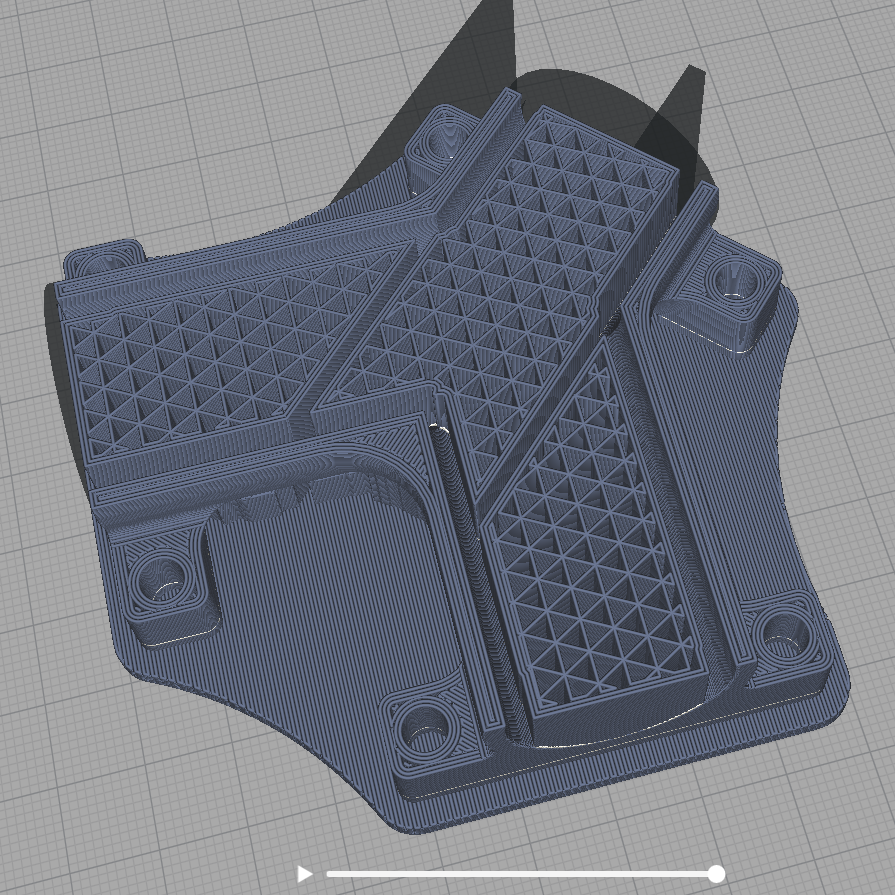 |
| Any regions that require metal support in multiple directions should be inspected after slicing to determine if it will be feasible to remove the support. | |
¶ Part Dimensions
Follow these general guidelines for better printing and sintering results. Be aware that the total bed mass should not be exceeding 3 kg/600cc.
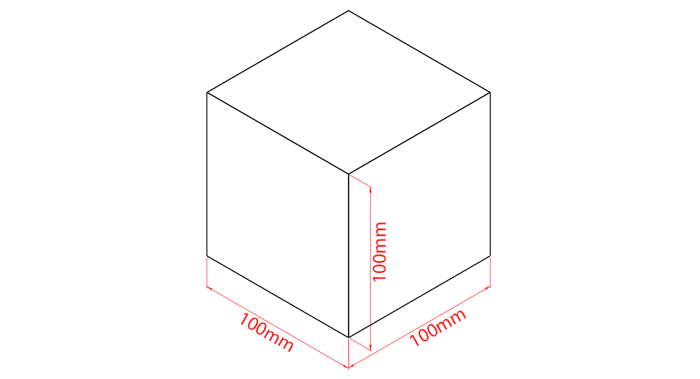 |
| Linear dimensions: parts under 10cm x 10cm x 10cm are easiest to sinter, with less severe distortion. |
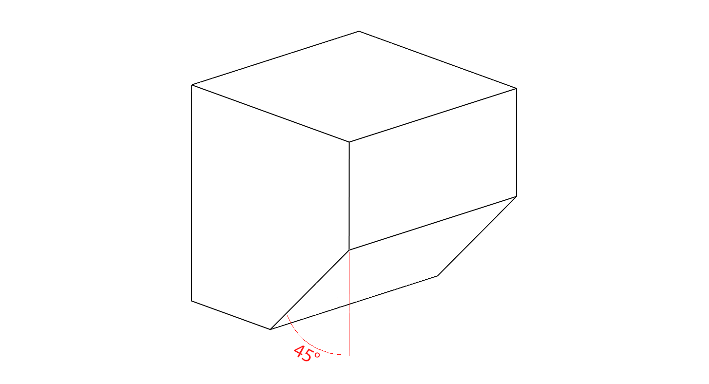 |
| Overhang angle: Unsupported overhangs should be smaller than 45 degrees. |
 |
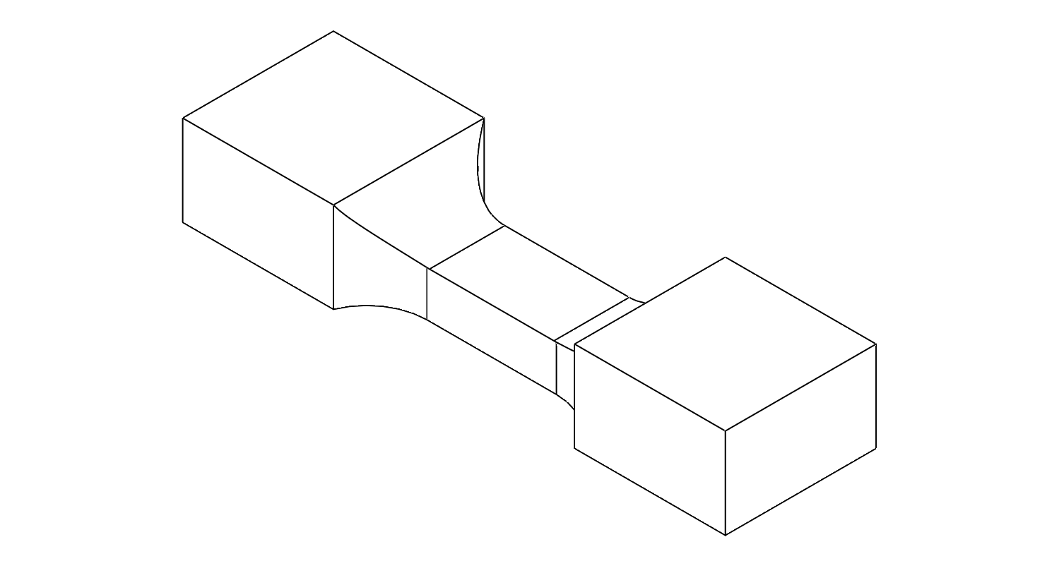 |
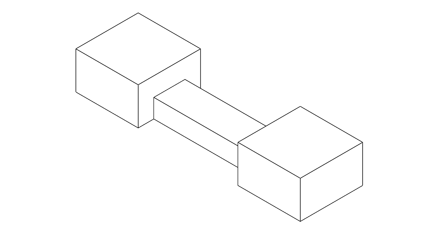
| Reduce sharp corners by filleting or chamfering where possible. | |
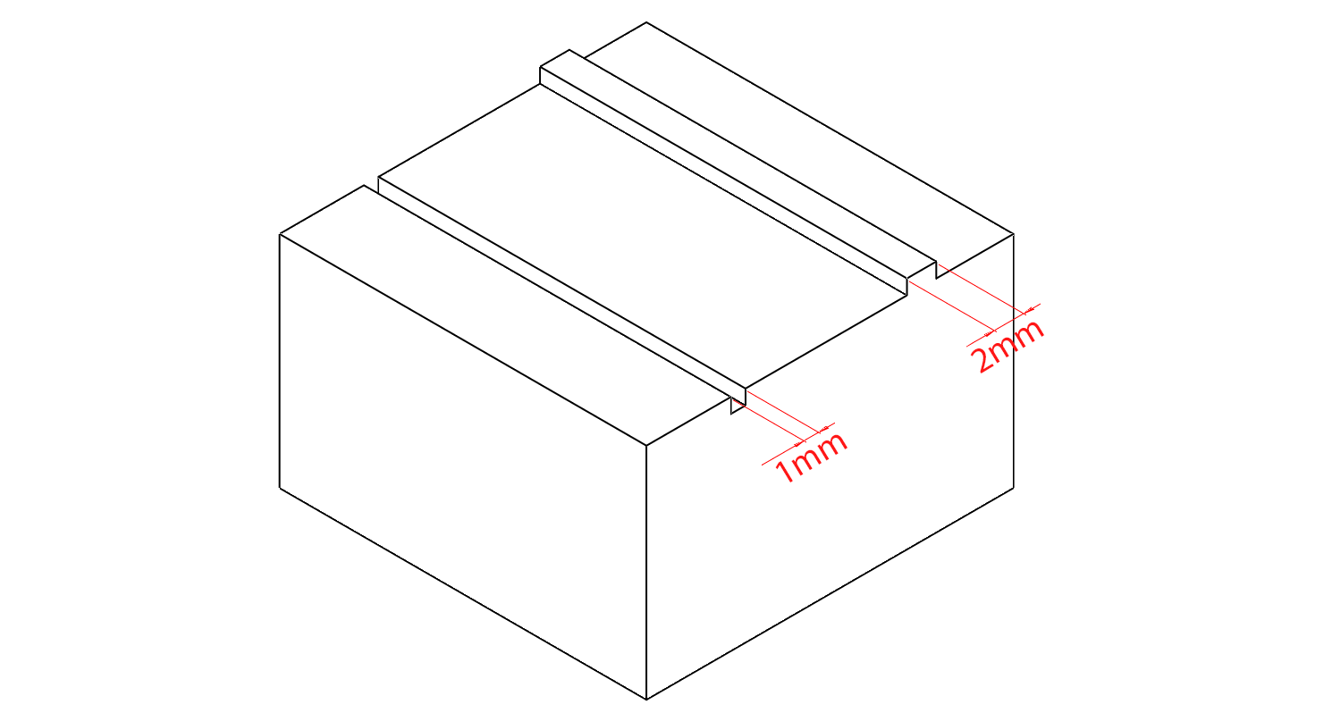 |
| Keep embossed features above 2mm. Keep engraved features above 1mm. |
 |
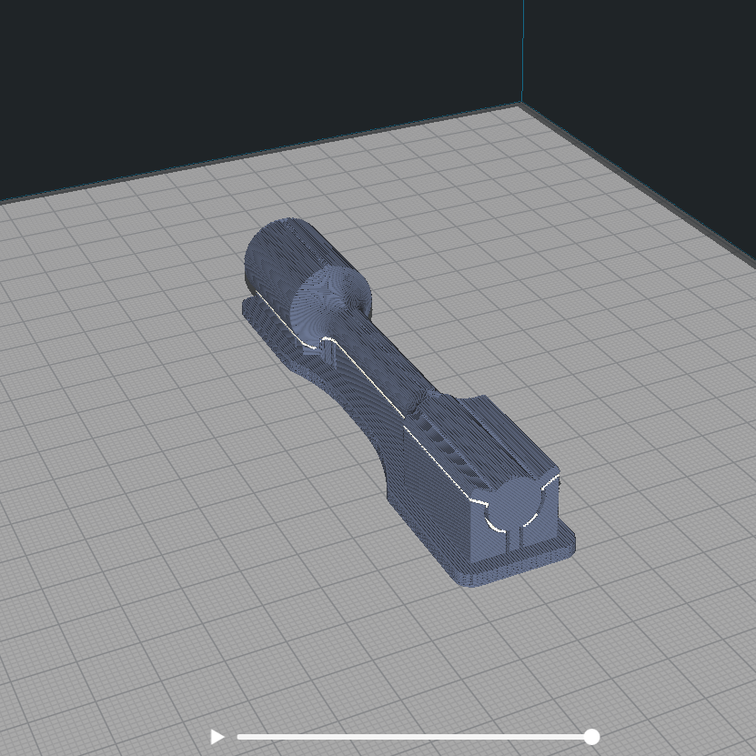 |
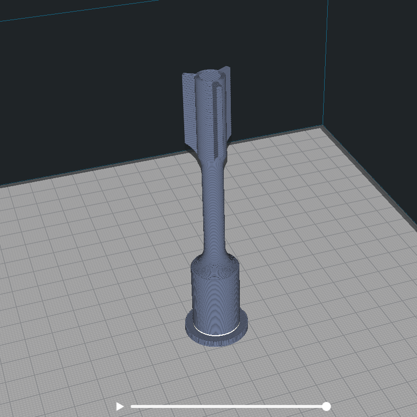
| Tall and thin parts should be sintered laying down. Avoid sintering parts vertically that have an aspect ratio greater than 2:1 as they will likely sag without special supports. | |
 |
 |
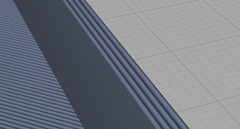 |
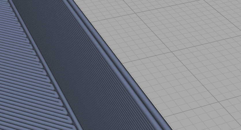
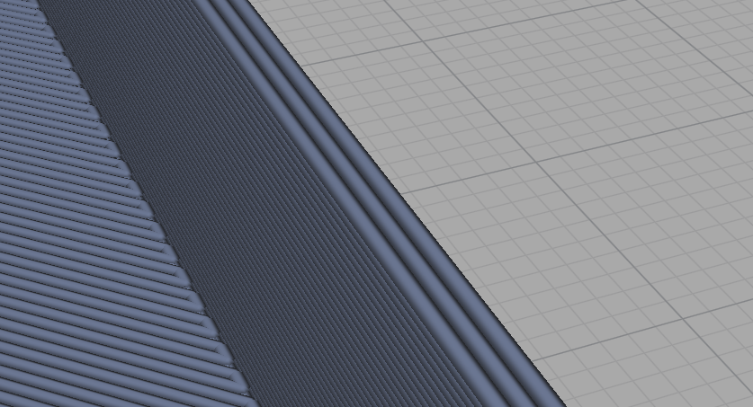
| Thin Walls: For the cleanest printed thin walls, their thickness should be an integer multiple of the nozzle diameter. | ||
¶ Example Guide
| Image | Dimensions [X , Y, Zed] (mm) | Level of Difficulty | Details | Additional Info |
|
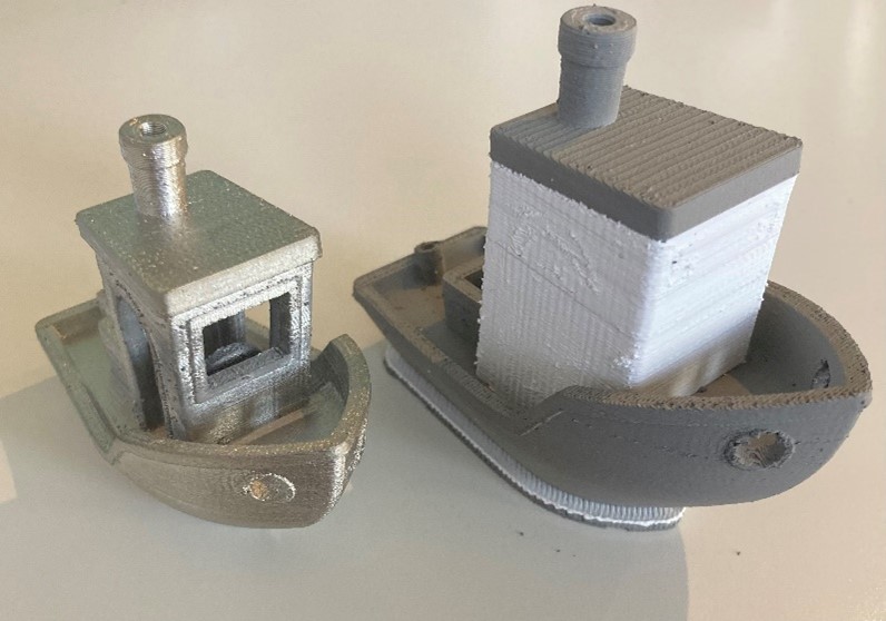 |
Printed: [42.8mm x 83.9mm x 65.6mm] Sintered: [36.8mm x 72.3mm x 56.5mm] Accuracy: [0.18%]X [0.1%]Y [0.05%]Zed |
Intermediate
|
Name: Metal Benchy Material Usage: 45cc Sintered Weight: 155g Cost of Material: $15.12 USD % Metal: 67 % Evaporative: 33 % Infill: 25 Print Time: 6hr 58min Sinter Cycle: Rapid Attempts before Success: 2 |
Settings changed: Support volume modifiers were added and the entire part was sliced with Evap-Support default settings.
This Benchy is a scaled up version of the normal FDM Benchy.
To assist general printer tuning. |
|
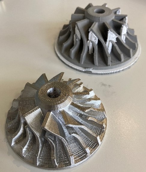 |
Printed: [73.9mm x 73.8mm x 31.3mm] Sintered: [63.6mm x 63.6mm x 27mm] Accuracy: [0.16%]X [0.03%]Y [0.00%]Zed |
Beginner | Name: Impeller Material Usage: 63.4cc Sintered Weight: 218g Cost of Material: $ USD % Metal: 94 % Evaporative: 6 % Infill: 100 Print Time: 8hr Sinter Cycle: Rapid Attempts before Success: None |
Settings changed: Concentric infill, Support overhang angle to 50
|
|
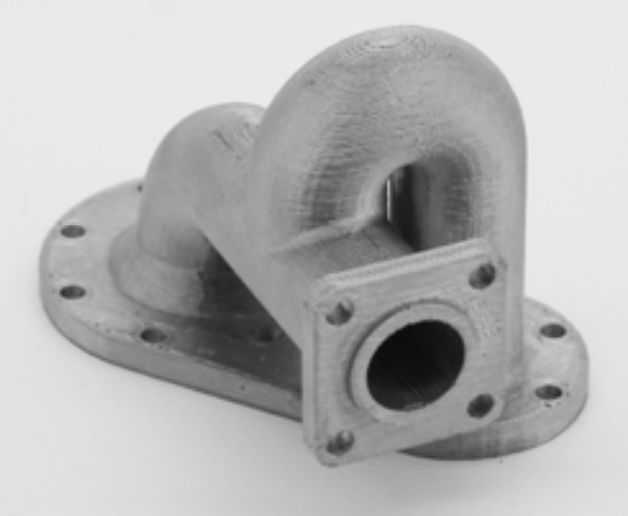 |
Printed: [80.2mm x 111.4mm x 71.6mm] Sintered: [69.1mm x 96mm x 61.7mm] Accuracy: [0.06%]X [0.07%]Y [0.11%]Zed |
Intermediate | Name: Dual Pipe Material Usage: 94cc Sintered Weight: 250g Cost of Material: $38 USD % Metal: 70 % Evaporative: 30 % Infill: 40 Print Time: 10hr 10min Sinter Cycle: Rapid Attempts before Success: 1 |
Settings changed: None
Custom support volume modifiers added for sintering support on large lever overhang of front sealing surface pipe.
|
|
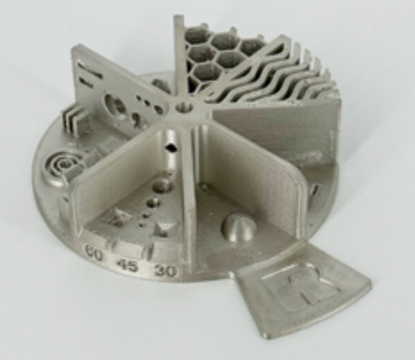 |
Printed: [53.3mm x 66.7m x 14.5mm] Sintered: [45.1mm x 57.5mm x 12.5mm] Accuracy: [0.06%]X [0.06%]Y [0.02%]Zed |
Expert | Name: Torture Test Material Usage: 112cc Sintered Weight: 500g Cost of Material: $45 USD % Metal: 95 % Evaporative: 5 % Infill: 100 Print Time: 12hr 29min Sinter Cycle: Rapid Attempts before Success: 12 |
Settings changed: None
|
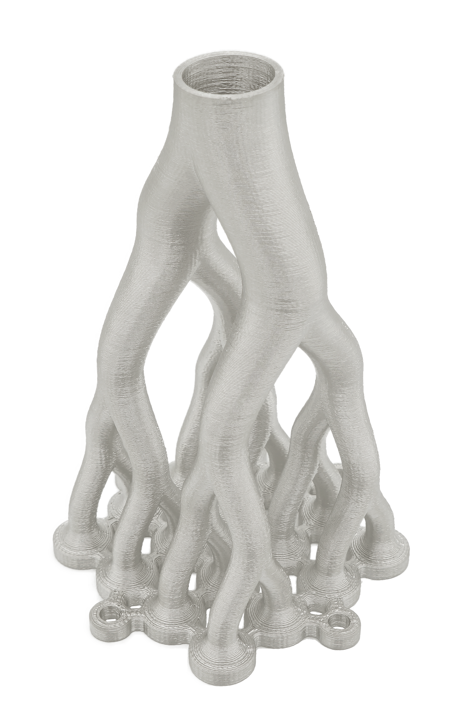 |
Printed: [86.8mm x 86.8mm x 129mm] Sintered: [74.8mm x 74.8mm x 112mm] Accuracy: [0.03%]X [0.03%]Y [0.04%]Zed |
Beginner | Name: Flow Distributor Material Usage: 105cc Sintered Weight: 280g Cost of Material: $40 USD % Metal: 96 % Evaporative: 4 % Infill: 25 Print Time: 11hr 45min Sinter Cycle: Rapid Attempts before Success: 1 |
Settings changed: Attempted to sinter without a raft, this friction caused the base to crack. A raft was added just as the default settings would recommend and it sintered well.
|
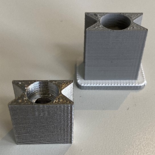 |
Printed: [11.5mm x 20.8mm x 22.2mm] Sintered: [9.9mm x 17.8mm x 19.1mm] Accuracy: [0.06%]X [0.67%]Y [0.1%]Zed |
Intermediate | Name: Small Mount Material Usage: 4.39cc Sintered Weight: 18g Cost of Material: $2.20 USD % Metal: 96 % Evaporative: 4 % Infill: 100 Print Time: 48min Sinter Cycle: Rapid Attempts before Success: 2 |
Settings changed: Wall Transitioning Threshold Angle to 17, Wall Order Outside to Inside, Z Seam Alignment User Specified
|
|
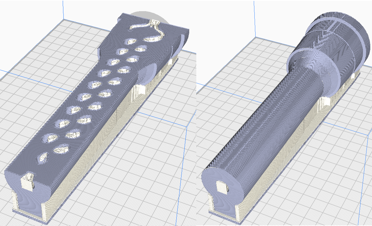 |
Printed: [61.8mm x 209.1mm x 58.5mm] Sintered: [53.1mm x 179mm x 50.4mm] Accuracy: [0.3%]X [0.8%]Y [0.06%]Zed |
Expert | Name: Cylindrical Heat Exchange Material Usage: 327cc Sintered Weight: 1350g Cost of Material: $134 USD % Metal: 94 % Evaporative: 6 % Infill: 100 Print Time: 29hr 41min Sinter Cycle: Standard Attempts before Success: 10 |
Settings changed: None
The metal support underneath generated with an interface layer resulted in sintering deformation. Eventually, CAD support to make the support a continuous feature in the same STL file resulted in a uniform shrinkage and successful part. This is an example of overcoming sintering issues seen in a part that is large, fully dense, with a high aspect ratio.
|