 |
 |
Respiratory/ chemical hazard: Fine particulates and powders present in the exhaust system pose a respiratory hazard. Chemical residues deposited in the exhaust system are harmful, avoid ingestion, inhalation, and skin contact. Wear nitrile gloves, goggles, and a respirator with cartridges for organic vapors and acids. |
 |
Flammability hazard: The residues collected in the binder trapping system and the exhaust of the furnace are flammable. Avoid open sparks or any other ignition sources. |
|
| Work in a well ventilated area, ideally under a fume hood. | ||
¶ Vacuum Exhaust System Overview
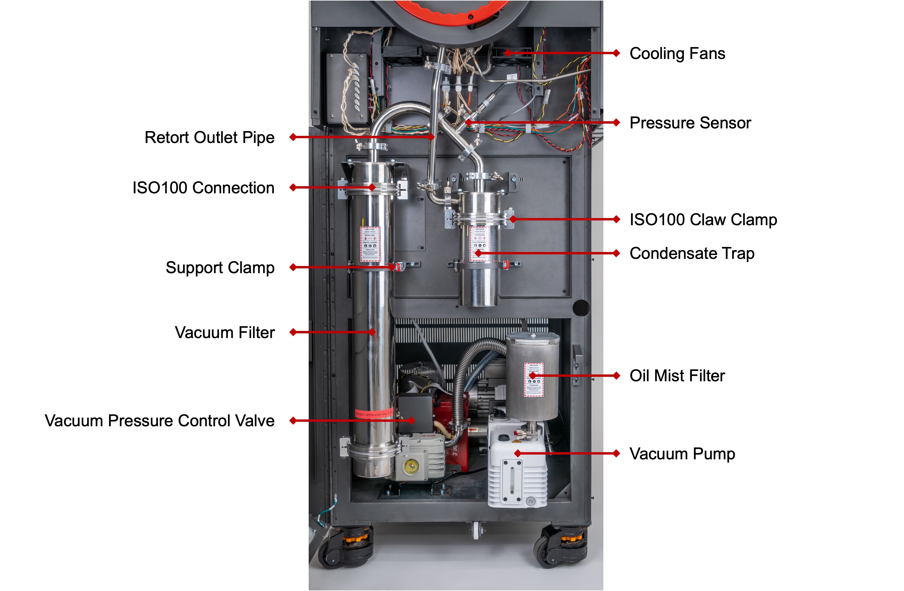
The furnace is fitted with a vacuum exhaust filtration system to collect byproducts from the debinding process and protect the vacuum pump. The system consists of a condensate trap, where easily condensable byproducts will settle, and a vacuum filter - all located behind the lower front door. The filter is filled with a proprietary blend of microporous molecular sieve media (Rapidia PN 100073), which scrubs volatile organics from the exhaust stream. The remaining exhaust gases are then emitted at the exhaust outlet port, which is to be properly vented to the exterior of the building. See Installation Requirements and Safety Hazards for more details.
Emptying The Condensate Trap
1. Power-off and unplug the furnace.
2. Open the lower front door and remove the middle front cover, below the retort, to expose the exhaust system:
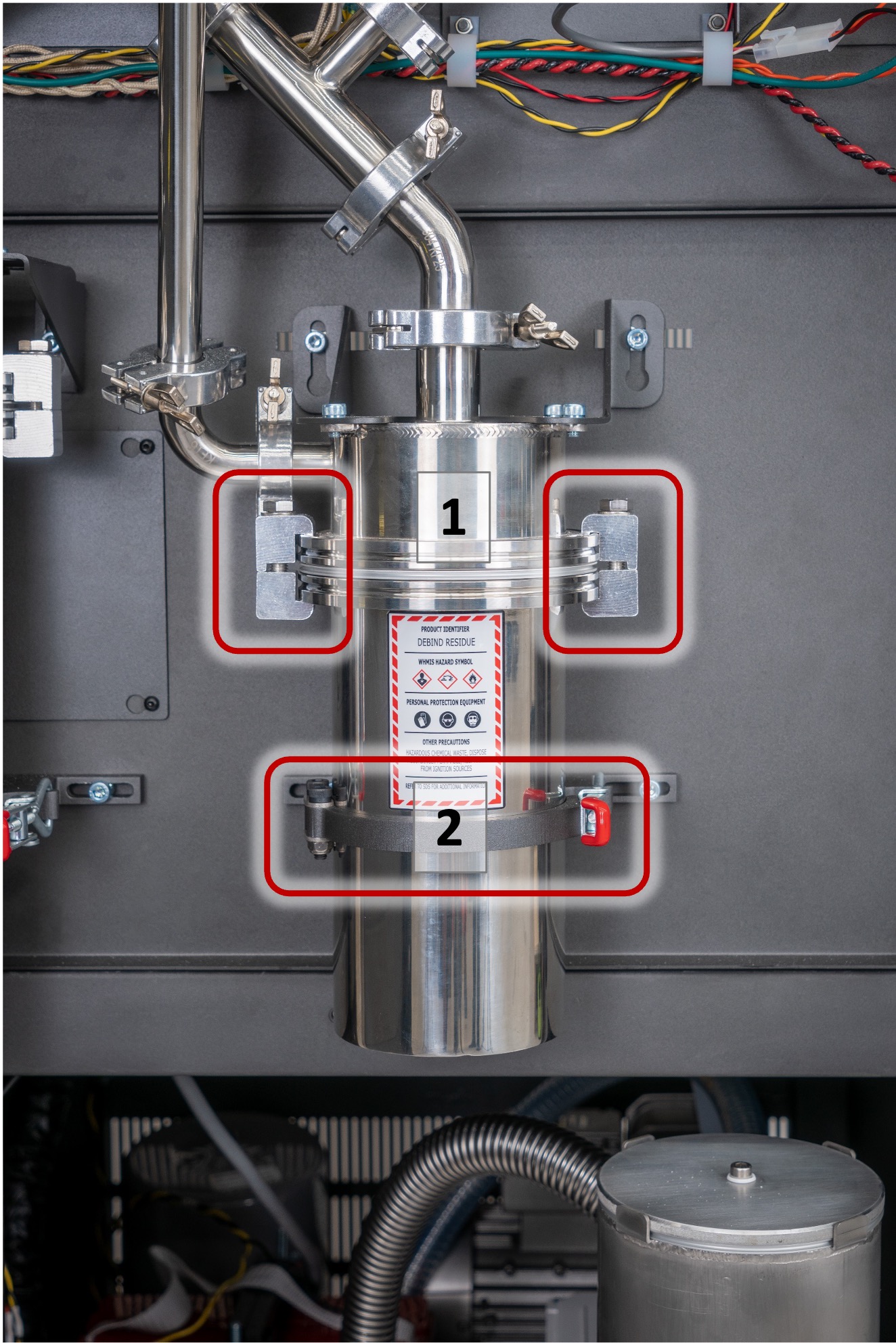
3. The condensate trap is removed by undoing the two claw clamps on the side of its ISO100 connection (13mm wrench), see 1 in image below. Once the claw clamps are removed, undo the support clamp (red handled latch) to remove the condensate trap, see 2 in image below.
Note: The condensate trap will contain liquid debind byproducts. Use care not to spill. Take care while opening any connections, some residue may begin to drip out right away.
4. Empty the condensate into a sealed container and dispose according to local environmental regulations for hazardous chemical waste disposal, incineration is appropriate if available.
5. Clean the ISO100 centering ring, and all sealing surfaces on ISO100 flanges. If the o-ring is damaged, replace with Viton Dash 346 o-ring (PN 9464K175).
Note: Do not use abrasive tools or materials when cleaning any sealing surfaces. Even small scratches across seals can cause vacuum leaks and poor sintering performance.
6. Before reinstalling Condensate Trap, continue with Replacing the Vacuum Filter Media and Cleaning The Retort Outlet Pipe.
¶ Replacing the Vacuum Filter Media
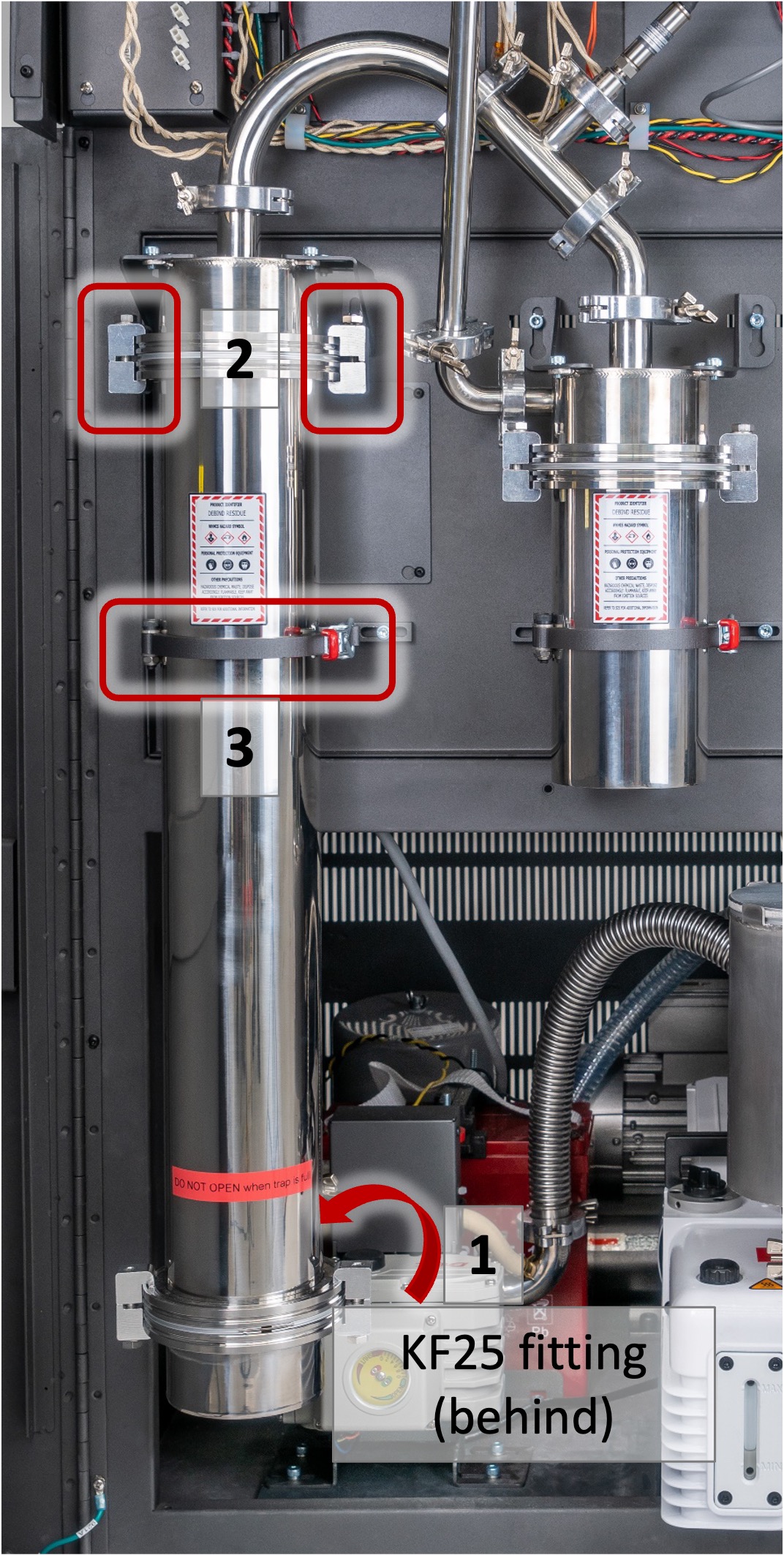
1. Undo the KF25 quick clamp on the outlet of the Vacuum Filter (at bottom hose connection to Vacuum Pressure Control Valve), see 1 in image below.
2. Undo the two ISO100 claw clamps at the top of the vacuum filter (13mm wrench), see 2 in image below.
Note: Do not undo the claw clamps at the bottom of the vacuum filter, or filter media will dump out.
3. While holding the Vacuum Filter, undo the support clamp and remove the full vacuum filter from the machine, see 3 in image below.
4. Remove the mesh screen centering ring from the top of the Vacuum Filter and set it aside.
5. Empty the used media into a sealed container and dispose according to local environmental regulations for hazardous chemical waste disposal. Wipe out the inside of the trap using lint free disposable towels and isopropanol and acetone solvent.
Tip: If used filter media remains stuck to the sides of the canister or to the bottom mesh screen, it may be helpful to open the lower ISO100 connection by removing the two lower claw clamps. With this connection open, you can scrape out any stubborn residues from the filter canister.
6. Clean the mesh screen centering ring(s) with isopropanol and acetone solvents, and compressed air. Clean the o-ring with a lint-free towel or replace with Viton Dash 346 o-ring (PN 9464K175).
7. If you opened the lower ISO100 connection, reassemble it with the mesh screen centering ring and a pair of claw clamps. Ensure that sealing surfaces on the flanges are perfectly clean before reassembly.
8. Take a new bag of filter media (Rapidia part no. 10000073), cut a corner of the bag to dispense the media blend and refill the trap. Use a wide-mouth funnel if necessary.
9. Clean any dust and residue from the upper ISO100 flange and set aside the Vacuum Filter for reinstallation after Cleaning The Retort Outlet Pipe.
¶ Cleaning The Retort Outlet Pipe
1. Remove the KF-16 outlet tube at the indicated fittings shown in image below.
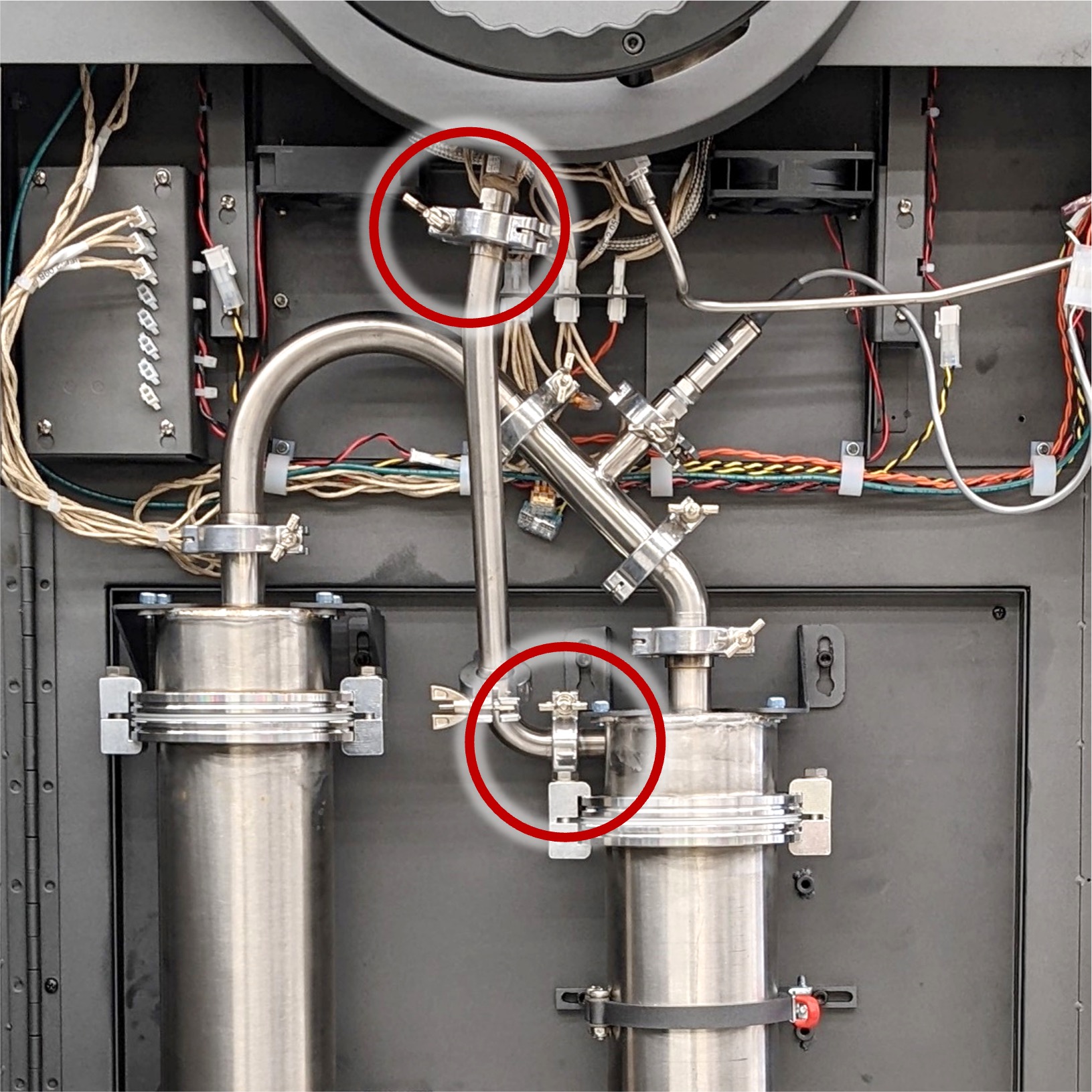
2. Disassemble the remaining KF16 connection to separate the outlet pipe and 90° elbow.
3. Clean all components removed in steps 1 & 2 using lint-free disposable towels, a wire/bottle brush, and isopropanol and acetone solvents as needed. They do not need to be spotless but be sure to remove the bulk of residue and deposit. See image below.
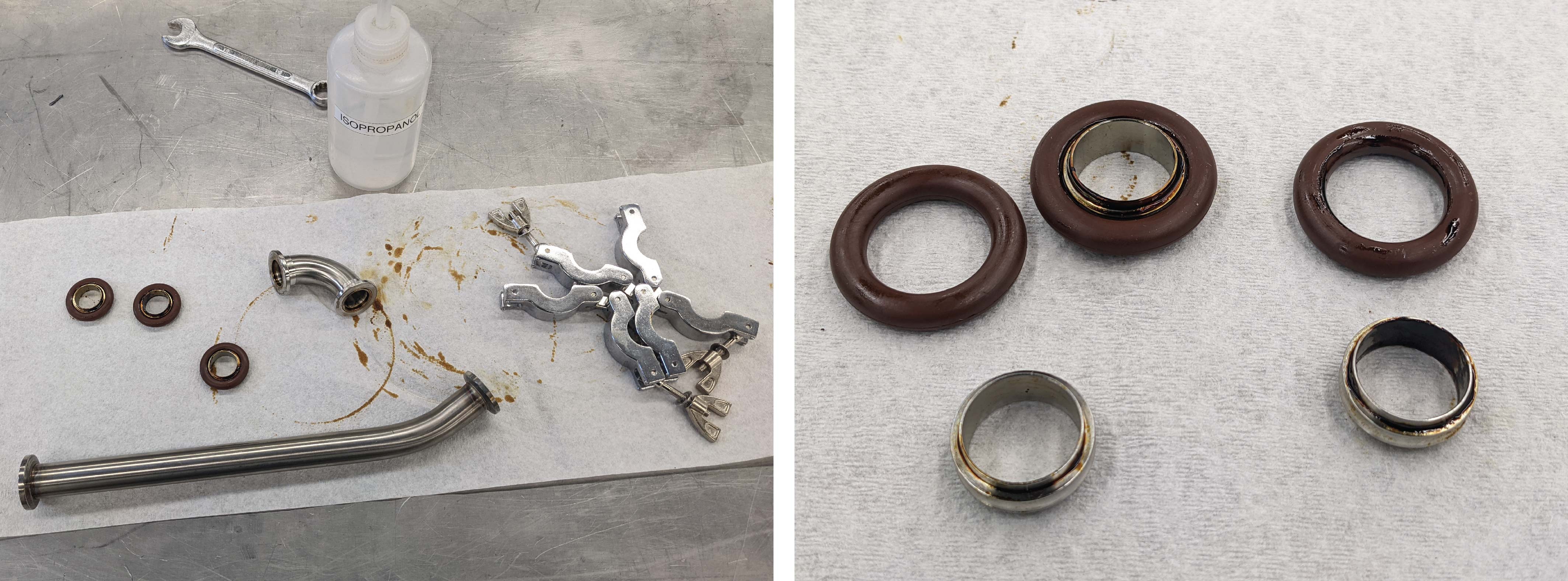
4. Using a bottle brush, lint-free disposable towels, and solvents, clean the Condensate Trap inlet pipe shown in image below.
5. Remove the sealing o-rings and replace them with fresh o-rings (see the rightmost image in image above: Cleaning the retort outlet pipe.)
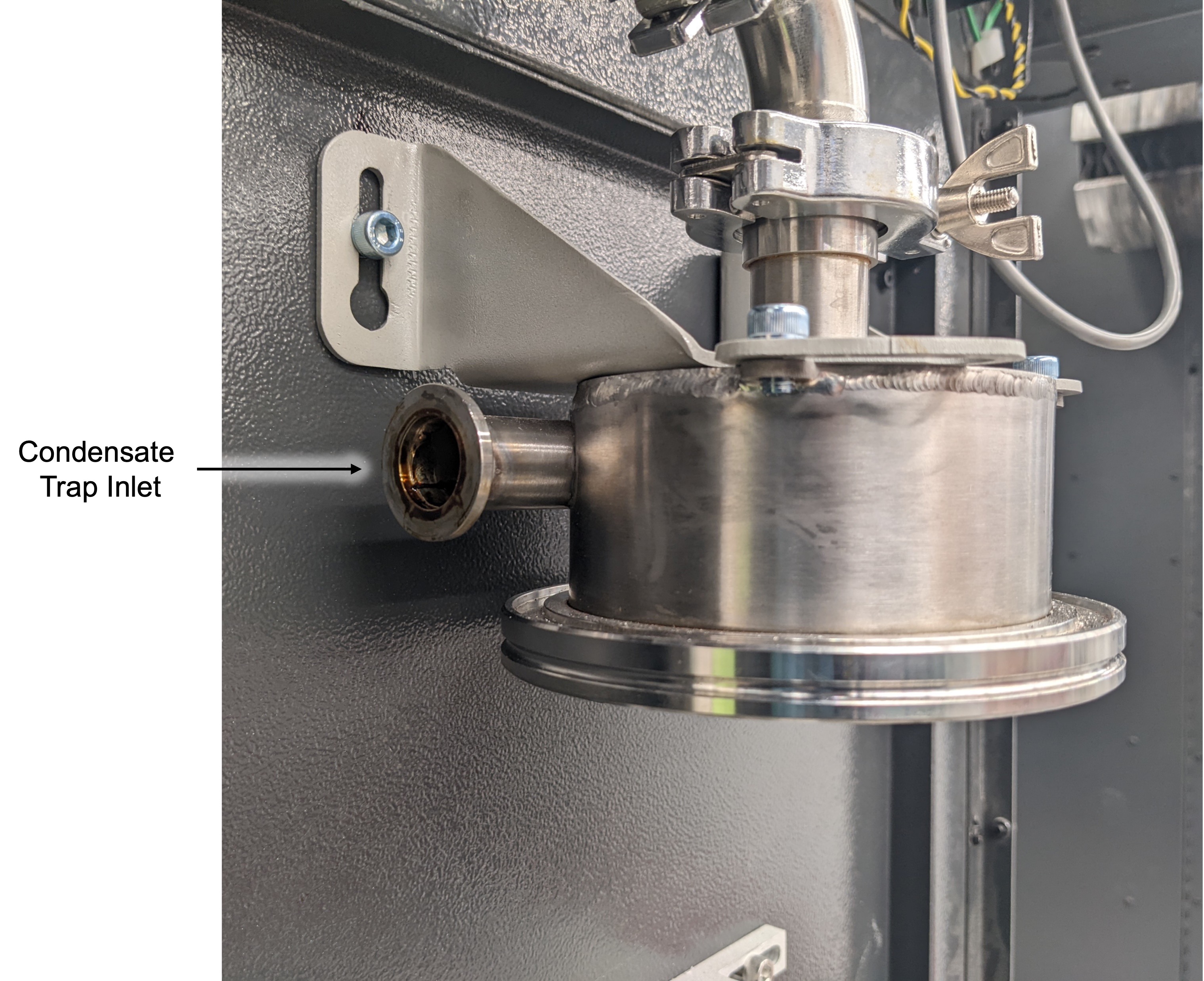
¶ Reassembly
1. Ensure all sealing surfaces and o-rings are clean before reassembly.
Note: Even a fine hair across a seal can cause a vacuum leak and poor sintering performance.
2. Begin reassembly by reconnecting the Retort Outlet pipe and 90° elbow. Leave the KF-clamp loose so that the fittings can rotate relative to each other for alignment.
3. Reconnect the Retort Outlet pipe and 90° elbow, rotating each fitting so that the centering rings align with each sealing face. Once all pieces are aligned, the KF-clamps can be tightened firmly.
4. Re-attach the Vacuum Filter as follows:
- Hold the trap in place. Fasten the support clamp in the middle of the canister.
- Tighten the two claw clamps at the top using a 13 mm hex wrench. Make sure they are positioned at about 180 degrees from each other as shown.
- Attach the outlet connection at the back, using the KF25 quick clamp.
5. Repeat steps 4a and 4b, this time with the Condensate Trap.
6. Double check that all connections are fully secured as they were at the start of the procedure.
7. Confirm that the system has been reassembled properly according to the setup shown in image above.